Full Bridge
The bridge circuit with PT100 consists of two fixed resistors and two variable resistors. It is called a “half bridge” because only half of the resistors contribute to the change in voltage with the physical quantity. This is because the resistance of a PT100 always increases when the temperature rises.
Let us look at a sensor whose resistance either increases or decreases with the physical quantity. This is the case, for example, with a strain gauge. A strain gauge consists of a conductive strip whose length can be either compressed (reduced) or stretched (increased). When the length l increases, its cross-sectional area A becomes somewhat smaller because the volume of the body stays constant. Because of the change in geometry when the length changes, the ohmic resistance of the strip changes, since:
The factor 2 in the equation comes from an approximation for the simultaneous increase in length and reduction of cross-sectional area when a body is pulled apart. We accept the factor without derivation; it does not play a major role later on.
A strain gauge is a sensor that behaves like a variable resistor. It has the properties length, cross-sectional area and its ohmic resistance. The formulas above refer to the resistance, which varies as the length and area change.
We use this sensor to build a scale. For this we use a beam that is firmly clamped on one side so that this end cannot move. The free end of the beam can move when a force acts on it. If something is placed on the free end, the beam bends under the weight.
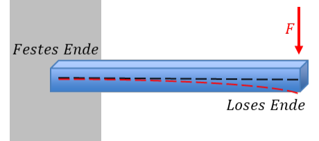
We glue one strain gauge to the top and another strain gauge of the same geometry to the underside of a beam. When the beam bends downwards, the upper sensor becomes longer and the lower one becomes shorter by about the same amount. For this, both ends of each strain gauge must be glued to the beam so that the middle part has to stretch or compress.
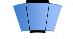
When a bending beam is loaded with a weight, it bends only minimally. The lengths of the strips also change very little.
When the physical quantity “weight” increases, the resistance of one strain gauge increases and that of the other decreases by the same amount. The identically constructed sensors behave in opposite ways because of their position on the beam. The resistance of both sensors is the same when the beam is completely straight, because their geometry is the same without bending.
(Oben = top, Unten = bottom.) The resistance R0 of all strain gauges with a straight beam corresponds to an offset. The change in length of the strain gauge is extremely small compared with its base length. So R0 ≫ ΔR applies. We are therefore faced with the problem that a very large offset dominates a tiny sensor signal.
We glue two strain gauges side by side on the top and two on the underside, because for a full bridge we need four strain gauges, two of which must behave in the opposite way to the other two. Then we connect the resistors in a bridge, lean back and admire the elegance of the mathematics:
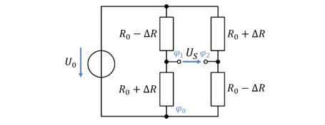
Without any approximation, we obtain a proportional relationship between sensor voltage and change in resistance. The offset R0 disappears completely from the formulas, as long as the geometry of all four resistors is the same with a straight beam.
The full bridge is twice as sensitive as the half bridge. The following applies:
For a change in resistance ΔR, the output voltage US of the full bridge changes twice as much as that of a half bridge. The full bridge is much better than the half bridge, which is why it is used in very many measurement systems. However, it requires resistors of which some become larger and others smaller as the physical quantity increases. In applications where this is not the case, we fall back on half bridges.