Voltage Measurement
The voltage – i.e. the difference between two potentials – is measured between two nodes in the circuit. For voltage measurement, the multimeter is connected in parallel with the resistor. According to the theory of the parallel connection, both then have the same voltage. In voltage measurement mode, the multimeter works as a "voltmeter". The symbol for a voltmeter is a circle with a V. The terminals on the real multimeter are the red socket (higher potential) and the black socket (lower potential).
For voltage measurement, you have to press the mode button until the "V" for volt to its left is highlighted in green.
The following figure shows an example circuit diagram in which you want to measure the voltage U2:
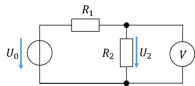
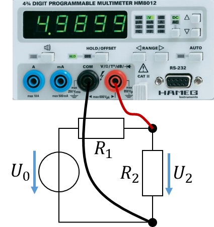
To do this, we connect the voltmeter – i.e. the multimeter in voltage measurement mode – in parallel with the resistor.
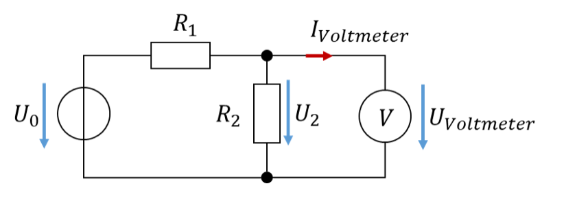
A measurement should not influence the function of the circuit. Therefore no current should flow from the circuit into the voltmeter, otherwise less current would be available at R2. Voltmeters are designed so that their input resistance is almost infinitely high. The current flowing into a voltmeter is therefore almost 0 A. You will learn this in the chapter on circuit analysis; if you do not understand it now, that is not a problem. With an infinitely high resistance, the following applies regardless of the value of the voltage: