This chapter discusses how differential signals can be amplified. For this we are looking for amplifier circuits that we can connect to a bridge circuit. The A/D converter needs a ground-referenced signal at its input. So the amplifier must convert a differential signal into a ground-referenced signal.
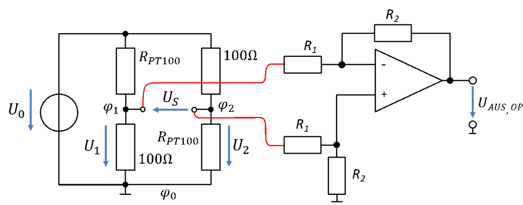
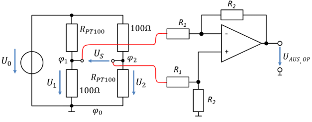
To amplify differential signals, we use a differential amplifier. If the output voltage of the half bridge with PT100 is connected to the inputs of the differential amplifier, the following circuit diagram results:
To derive the transfer function, let us assume that the ground-referenced voltages U1 and U2 shown are applied at the inputs of the differential amplifier (on the red lines). These voltages correspond to the potentials from the previous chapter. Then the output voltage is:
The transfer function can now be adjusted with the resistor values. We can create any slope of the characteristic curve. The output voltage of the op-amp is ground-referenced and can therefore be digitised by an ADC.
Example
\[
\begin{gathered}
\text{Given:} \\[6pt]
\text{Temperature range: } T = [0\,°\mathrm{C} \ldots 100\,°\mathrm{C}] \\[6pt]
\text{Reference voltage of the ADC: } U_{\mathrm{Ref}} = 5\,\mathrm{V} \\[6pt]
U_0 = 5\,\mathrm{V}
\end{gathered}
\]
\[
\begin{gathered}
\textbf{Solution with approximation:} \\[6pt]
H = \frac{U_{\mathrm{Aus,OP}}}{T} \approx v \cdot U_0 \cdot \frac{0.4\,\frac{\Omega}{°\mathrm{C}}}{200\,\Omega} \\[6pt]
\text{Calculating the output voltage of the op-amp:} \\[6pt]
U_{\mathrm{Aus,OP}} = H \cdot T = v \cdot U_0 \cdot \frac{0.4\,\frac{\Omega}{°\mathrm{C}}}{200\,\Omega} \cdot T \\[6pt]
v = \frac{U_{\mathrm{Ref}}}{U_{S,\mathrm{max}}} = \frac{5\,\mathrm{V}}{U_0 \cdot \frac{0.4\,\frac{\Omega}{°\mathrm{C}}}{200\,\Omega} \cdot 100\,°\mathrm{C}} = \frac{5\,\mathrm{V}}{1\,\mathrm{V}} = 5 \\[6pt]
\text{Solution: e.g. } R_1 = 1\,\mathrm{k\Omega} \text{ and } R_2 = 5\,\mathrm{k\Omega}
\end{gathered}
\]
\[
\begin{gathered}
\textbf{Solution without approximation:} \\[6pt]
U_S = U_0 \cdot \frac{0.4\,\frac{\Omega}{°\mathrm{C}} \cdot T}{200\,\Omega + 0.4\,\frac{\Omega}{°\mathrm{C}} \cdot T} \\[6pt]
\text{Calculating the output voltage of the op-amp:} \\[6pt]
U_{\mathrm{Aus,OP}} = v \cdot U_S = v \cdot U_0 \cdot \frac{0.4\,\frac{\Omega}{°\mathrm{C}} \cdot T}{200\,\Omega + 0.4\,\frac{\Omega}{°\mathrm{C}} \cdot T} \\[6pt]
v = \frac{U_{\mathrm{Ref}}}{U_{S,\mathrm{max}}} = \frac{5\,\mathrm{V}}{U_0 \cdot \frac{0.4\,\frac{\Omega}{°\mathrm{C}} \cdot 100\,°\mathrm{C}}{200\,\Omega + 0.4\,\frac{\Omega}{°\mathrm{C}} \cdot 100\,°\mathrm{C}}} = \frac{5\,\mathrm{V}}{0.83\,\mathrm{V}} = 6 \\[6pt]
\text{Solution: e.g. } R_1 = 1\,\mathrm{k\Omega} \text{ and } R_2 = 6\,\mathrm{k\Omega}
\end{gathered}
\]
The approximation is quite drastic, and the approximated result is rather far from the real result. We use it for rough estimates in practice and for calculating exam problems.