Operation with a Current Source
The PT100 measuring resistor is connected in series with a current source.

The characteristic of the sensor voltage versus temperature looks like this:
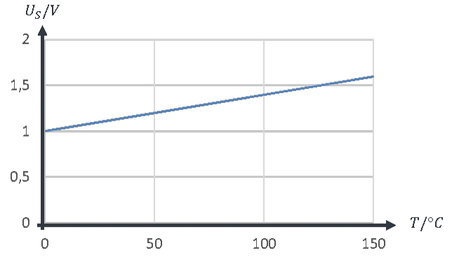
The sensor voltage rises linearly from an initial value of 1 V. The behaviour is already better than in the voltage divider, but not proportional, because the voltage curve starts at 1 V and not at 0 V. Because the resistance at T = 0 °C has the value R = 100 Ω, the voltage must have an offset of U(T = 0 °C) = 100 Ω ∙ 10 mA = 1 V. Note: in practice, a smaller measuring current (e.g. 1 mA) is usually chosen so that the sensor does not heat itself up through the power dissipated in it.
This solution requires a current source. An accurate current source is a complex circuit that causes cost and effort. In addition, the offset is very high compared with the change in voltage with temperature. The input voltage range of the AD converter is not used optimally. We are looking for a solution without an offset voltage. It can be done even better. But for that, you still need some fundamentals. We come back to this topic with the bridge circuit a few chapters later. Until then, we work with the best of the solutions discussed so far: operation on the current source.