Voltage Divider
In the simplest case, the voltage divider is a circuit consisting of two resistors R1 and R2 connected in series. In the series connection, the input voltage U0 is divided among the components connected in series. The same current I0 flows through all components.
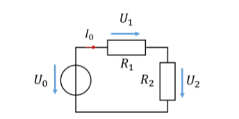
With the two bottom formulas, it is possible to calculate a partial voltage in the series connection if only the total voltage is available. To do this, we need to know all resistances. It is not necessary to know the current in the series connection. This is sometimes handy for calculations in a circuit in which the current has not (yet) been calculated.
The voltage divider is an aid to calculation. You can also obtain all values for voltage and current with the mesh equation and Ohm's law. So it does not provide any new information. However, the voltage divider also helps you to understand intuitively how the voltage in a series connection is divided between the resistors. Let us look at the voltage divider formulas once more:
The partial voltage across a resistor (e.g. U1) equals the total voltage across both resistors (U0) multiplied by a factor. The factor consists only of resistance values. The sum in the denominator is the same for both factors. The two factors differ in the numerator.
The factors are smaller than 1. That is why a partial voltage is always smaller than the total voltage. Their range of values is [0 .. 1]. The sum of the partial voltages gives the total voltage. So the sum of the two factors must be 1. Pairs such as factor1 = 0.3 and factor2 = 0.7 can occur. Then the total voltage is divided in a ratio of 3 to 7. Or the factors are factor1 = 0.5 and factor2 = 0.5. Then the voltage is divided equally between both resistors.
The size of the resistance R1 relative to the size of R2 determines how the voltage is divided. Let us look at an example:
From the values of the resistors, you can see directly how the voltage is divided in the series connection. I find that pretty cool. This lets us see much more easily how a voltage is divided in complex circuits than with the mesh equation and Ohm's law.
Use in a circuit
A voltage divider converts an input voltage that is too high into a suitable lower voltage. This can be used, for example, to operate a lamp with a desired voltage of ULampe = 3 V from a battery with an output voltage of UBatt = 3.7 V. For this example, we model the lamp as a resistor with RLampe = 1 Ω. We solve the problem with a voltage divider. To do this, we have to dimension the second resistor of the voltage divider. The following applies:

With an additional resistor R1 = 0.233 Ω in series with the lamp, we have reduced the voltage from 3.7 V to 3 V. Rearranging the voltage divider equation is not trivial; solve it on a piece of paper as an exercise. The numerical values above do not apply in general, but only to this example.
The voltage divider formula only applies to circuits in which exactly two components are connected in series. Let us look at a circuit with more than two components in series. Suppose we absolutely want to work with the voltage divider (which in this case is not the easiest way to the goal). Then we have to combine resistors until only two resistors are left. Here is an example of this as well:

If the voltage U3 is required in the example, the circuit is simplified as follows:
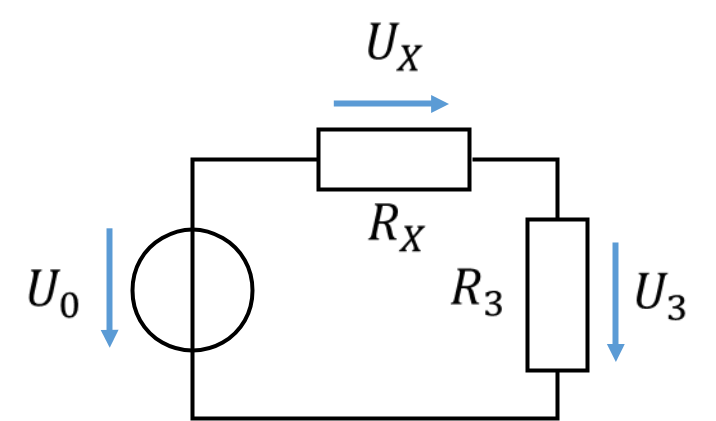
Now the circuit is in the standard form in which the voltage divider formula can be used. To determine partial voltages in a complex circuit, it is helpful to transform the circuit so that the voltage divider formula can be applied.
Alternatively, the voltage U3 could also have been calculated via the current I0:
This route is mathematically simpler. The partial voltage across a resistor can be calculated somewhat more generally with the formula given above. It also applies to more than 2 resistors in series.
A voltage divider is not always intended by the designer of a circuit. It often arises unintentionally in circuits. The important insight is that in every series connection of resistors – intended or not – the total voltage is divided according to the size of the resistors.
Problem: Calculate all partial voltages in the following circuit, both in general and numerically.
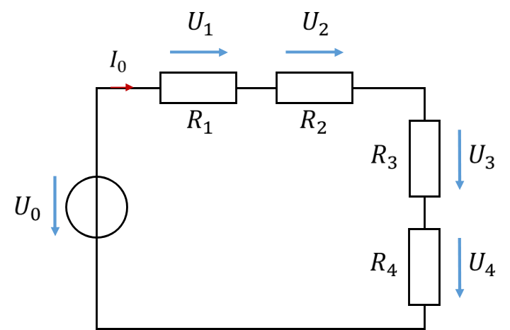
Solution:
The same voltage is present across each resistor, because the resistors are equal in size.