Learning Content and Theses

Platform for digital learning at HSHL

Calculating with Reactances

Let us now look at the voltages across a resistor, an inductor and a capacitor when the current is a sine:

Resistor

\[ \begin{gathered} i(t) = 1\,\mathrm{mA} \cdot \sin(\omega t) \\[4pt] \text{Resistor: } R = 10\,\Omega \\[4pt] u_R(t) = R \cdot i(t) = 10\,\Omega \cdot 1\,\mathrm{mA} \cdot \sin(\omega t) = 10\,\mathrm{mV} \cdot \sin(\omega t) \\[4pt] \text{Peak value: } \hat{u}_R = R \cdot \hat{\imath} = 10\,\Omega \cdot 1\,\mathrm{mA} = 10\,\mathrm{mV} \end{gathered} \]

For a resistor, the voltage is a sine if the current is a sine.

Capacitor

\[ \begin{gathered} \text{Current: } i(t) = 1\,\mathrm{mA} \cdot \sin(\omega t) \\[4pt] \text{Capacitance: } C = 100\,\text{µF} \\[4pt] f = 50\,\mathrm{Hz} \rightarrow \omega = 2\pi f = 314\,\frac{1}{\mathrm{s}} \\[6pt] X_C = \frac{1}{\omega C} = \frac{1}{314\,\frac{1}{\mathrm{s}} \cdot 100\,\text{µF}} = 31.83\,\Omega \\[6pt] \text{Peak value: } \hat{u}_C = X_C \cdot \hat{\imath} = 31.83\,\Omega \cdot 1\,\mathrm{mA} = 31.83\,\mathrm{mV} \end{gathered} \]

What waveform will the capacitor voltage have if the current is a sine? The current is integrated, and the integral of sine is “minus cosine”. The following applies:

\[ \begin{gathered} u_C(t) \sim \int i(t)\,dt = \int \sin(\omega t)\,dt \sim -\cos(\omega t) \\[6pt] u_C(t) = \color{#c00000}{-}\hat{u}_C \cdot \cos(\omega t) = \color{#c00000}{-}31.83\,\mathrm{mV} \cdot \cos(\omega t) \end{gathered} \]

If the current in the capacitor is a sine, the voltage is a “minus cosine”.

Inductor

\[ \begin{gathered} \text{Current: } i(t) = 1\,\mathrm{mA} \cdot \sin(\omega t) \\[4pt] \text{Inductance: } L = 10\,\mathrm{mH} \\[4pt] f = 50\,\mathrm{Hz} \rightarrow \omega = 2\pi f = 314\,\frac{1}{\mathrm{s}} \\[6pt] X_L = \omega L = 314\,\frac{1}{\mathrm{s}} \cdot 10\,\mathrm{mH} = 3.14\,\Omega \\[6pt] \text{Peak value: } \hat{u}_L = X_L \cdot \hat{\imath} = 3.14\,\Omega \cdot 1\,\mathrm{mA} = 3.14\,\mathrm{mV} \end{gathered} \]

What waveform will the inductor voltage have if the current is a sine? The current is differentiated, and the derivative of sine is cosine. The following applies:

\[ \begin{gathered} u_L(t) \sim \frac{di}{dt} = \frac{d}{dt} \sin(\omega t) \sim \cos(\omega t) \\[6pt] u_L(t) = \hat{u}_L \cdot \cos(\omega t) = 3.14\,\mathrm{mV} \cdot \cos(\omega t) \end{gathered} \]

If the current in the inductor is a sine, the voltage is a (positive) cosine.

Capacitor and inductor behave the same apart from the sign: they turn a sinusoidal current into a ± cosine voltage. A resistor turns a sinusoidal current into a sinusoidal voltage.

Addition and multiplication of resistance and reactance

For example, to calculate the total resistance in a series connection, we have to add resistances. In a parallel connection, we have to add and multiply. In DC networks, the following applies:

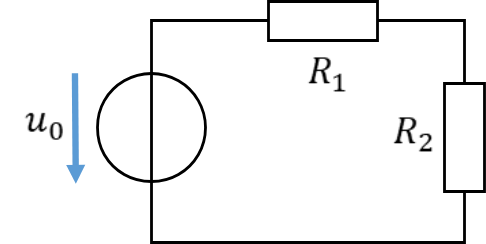
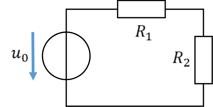
Series connection of R1 and R2
\[ \text{Series connection: } R_{\mathrm{Ges}} = R_1 + R_2 \]
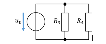
Parallel connection of R3 and R4
\[ \text{Parallel connection: } R_{\mathrm{Ges}} = \frac{R_3 \cdot R_4}{R_3 + R_4} \]

If we consider resistances and reactances more generally, we also have to add and multiply them. The following rules apply:

There are no special rules for multiplication; resistances and reactances can be multiplied with each other freely.

\[ \begin{gathered} R \cdot X_C \\[4pt] R \cdot X_L \\[4pt] X_L \cdot X_C \end{gathered} \]

A resistance is added to another resistance “normally”.

Series connection of R1 and R2
\[ R_{\mathrm{Ges}} = R_1 + R_2 \]

A resistance is added to a reactance (inductor or capacitor) in quadrature.

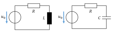
Series connection of R and L and of R and C
\[ \begin{gathered} \text{Capacitor: } X_{\mathrm{Ges}} = \sqrt{R^2 + X_C^2} \\[6pt] \text{Inductor: } X_{\mathrm{Ges}} = \sqrt{R^2 + X_L^2} \end{gathered} \]

A reactance is added to another reactance “normally”. The reactance of an inductor counts as positive and that of a capacitor as negative.

Series connection of C and L
\[ X_{\mathrm{Ges}} = X_L - X_C \]

Reactances describe energy stores which, when integrating or differentiating, turn a sine into a cosine and vice versa. If a sinusoidal current flows through two reactances, the inductor turns it into a “plus cosine” voltage and the capacitor turns it into a “minus cosine” voltage. That is why the inductor reactance is added as positive and the capacitor reactance as negative.

Examples

First, we define a few components with which we then calculate by way of example.

\[ \begin{gathered} \text{Resistor } R = 1\,\Omega \\[4pt] \text{Inductor: } L = 6.36\,\mathrm{mH} \\[4pt] \text{Capacitor: } C = 3.18\,\mathrm{mF} \\[4pt] f = 50\,\mathrm{Hz} \rightarrow \omega = 2\pi f = 314\,\frac{1}{\mathrm{s}} \\[6pt] X_L = \omega L = 314\,\frac{1}{\mathrm{s}} \cdot 6.36\,\mathrm{mH} = 2\,\Omega \\[6pt] X_C = \frac{1}{\omega C} = \frac{1}{314\,\frac{1}{\mathrm{s}} \cdot 3.18\,\mathrm{mF}} = 1\,\Omega \end{gathered} \]

Inductor L and resistor R

\[ \begin{gathered} \text{Series connection: } X_{\mathrm{Ges}} = \sqrt{R^2 + X_L^2} = \sqrt{(1\,\Omega)^2 + (2\,\Omega)^2} = 2.24\,\Omega \\[6pt] \text{Parallel connection: } X_{\mathrm{Ges}} = \frac{R \cdot X_L}{\sqrt{R^2 + X_L^2}} = \frac{1\,\Omega \cdot 2\,\Omega}{2.24\,\Omega} = 0.89\,\Omega \end{gathered} \]

Simulation

Capacitor C and resistor R

\[ \begin{gathered} \text{Series connection: } X_{\mathrm{Ges}} = \sqrt{R^2 + X_C^2} = \sqrt{(1\,\Omega)^2 + (1\,\Omega)^2} = 1.41\,\Omega \\[6pt] \text{Parallel connection: } X_{\mathrm{Ges}} = \frac{R \cdot X_C}{\sqrt{R^2 + X_C^2}} = \frac{1\,\Omega \cdot 1\,\Omega}{1.41\,\Omega} = 0.7\,\Omega \end{gathered} \]

Simulation

Inductor L and capacitor C

\[ \begin{gathered} \text{Series connection: } X_{\mathrm{Ges}} = X_L - X_C = 2\,\Omega - 1\,\Omega = 1\,\Omega \\[6pt] \text{Parallel connection: } X_{\mathrm{Ges}} = \frac{X_L \cdot X_C}{X_L - X_C} = \frac{2\,\Omega \cdot 1\,\Omega}{2\,\Omega - 1\,\Omega} = 2\,\Omega \end{gathered} \]

Simulation

We define the reactance mainly so that we can calculate with alternating current almost as easily as with direct current. It is a mathematical simplification. However, it also describes the behaviour of the components with alternating current. A reactance is an AC resistance. It indicates how much resistance a component offers to alternating current. With a larger reactance, less current flows.
Download course as PDF

The PDF contains all pages of the course. Interactive content is only available on the website.