Non-Inverting Amplifier
The behaviour of an op-amp is determined solely by the external circuit. First, we look at the non-inverting amplifier, whose circuit diagram looks like this:
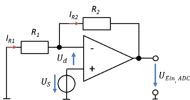
We model the output signal of the sensor as a voltage source US. In this circuit, we connect it to the non-inverting input of the op-amp. In practice, you therefore run a cable between the sensor output and this op-amp input. The output of the op-amp is connected directly to the ADC input. The names of the voltages indicate where the signals are processed further. To remain consistent with the naming convention from the beginning of the chapter, from now on I call the source at the input UEIN,OP and the output voltage of the op-amp UAUS,OP.
Many ground symbols are used in this circuit diagram. Ground only indicates that the potential at this point of the circuit is φ = 0 V. All points of the circuit with a ground symbol are connected to each other by conductors. Out of laziness, we do not draw these connections in the circuit diagram. You have to imagine all these points connected to each other. In the lab, you must connect all these points with cables. Traditionally, we use black cables for ground.
We have a voltage source at the input of the op-amp whose lower terminal is at ground potential. This means that the potential at the upper terminal is higher than 0 V by the value US. At the output there is a voltage whose voltage arrow is drawn to ground. In the circuit, we refer all potentials and voltages to ground. An output voltage of UAus,OP = −1 V therefore means that the potential at the output of the op-amp is 1 V below ground.
To calculate the behaviour, we first set up two mesh equations.
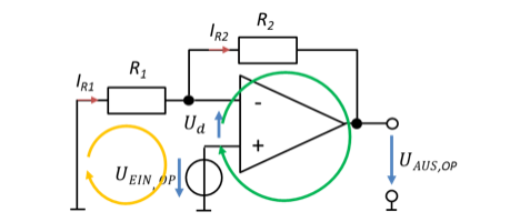
As a result, we obtain the relationship between the input and output voltage of this circuit. The input signal is transferred to the output multiplied by the factor v.
An input voltage is multiplied by an adjustable gain v. We set the value of the gain freely with the resistors. That is brilliant: we can set the gain of the op-amp solely through the external circuit with resistors. It does not matter at all which op-amp is used. Only the resistors matter.
The non-inverting amplifier cannot attenuate a signal, because the gain v is always at least 1. To make it smaller than 1, we would need negative resistors, which do not exist. To attenuate a signal, we need a gain in the range v = [0 .. 1]. So we still need further amplifier circuits.