Kirchhoff’s Voltage Law
There are different potentials in a circuit. Let us take the circuit below as an example. The highest potential in the circuit, φ1, is above the source. The potential φ6 below the source is the lowest potential.
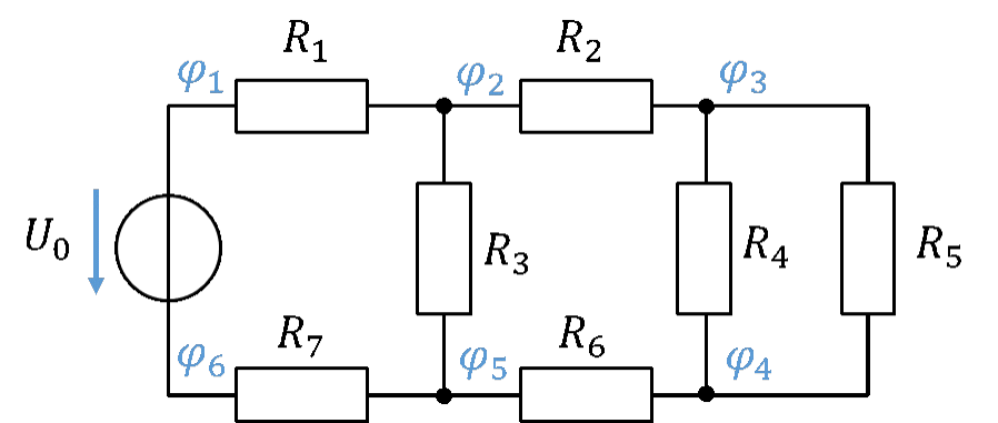
The current I1 flows through the resistor R1. According to Ohm's law, this current causes the voltage U1 to drop across R1.
So the potential φ2 at the next node is lower than φ1 directly at the source. In the water model analogy, the potential φ1 is the height of the mountain lake where the river rises. φ6 is at sea level. The river flows through the first riverbed R1 towards the sea. In doing so it loses some height, so the height at the end of this section of the riverbed must be lower than that of the mountain lake.
The river now splits into two branches I2 and I3, whose riverbeds are different. The potential φ5 is lower than φ2 but higher than φ6, because the current has flowed from top to bottom (from φ2 towards φ5) through the resistor R3. A voltage of U3 = R3 ∙ I3 has dropped across R3. The further you walk along the river in the direction of flow (current direction), the lower the height (the potential).
Kirchhoff's voltage law (mesh rule) brings a system into the potentials and voltages. A mesh is a closed loop in a circuit along conductors in which each component and each node may be included only once.
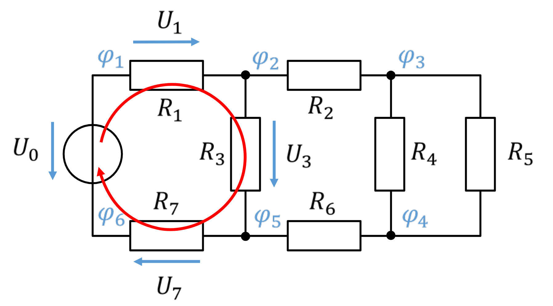
According to this definition, the path drawn in red along the conductors forms a mesh, because no component in the loop is passed through more than once. In a mesh, the mesh equation applies, according to which the sum of the voltages around the loop equals 0 V. Voltages in the clockwise direction are counted as positive, those in the anticlockwise direction as negative. In this example, the following applies to the red mesh:
If, for example, the voltages U0, U1 and U3 have already been calculated, the voltage
can be calculated from this mesh equation. Another mesh is drawn in green in the figure below. The mesh equation is
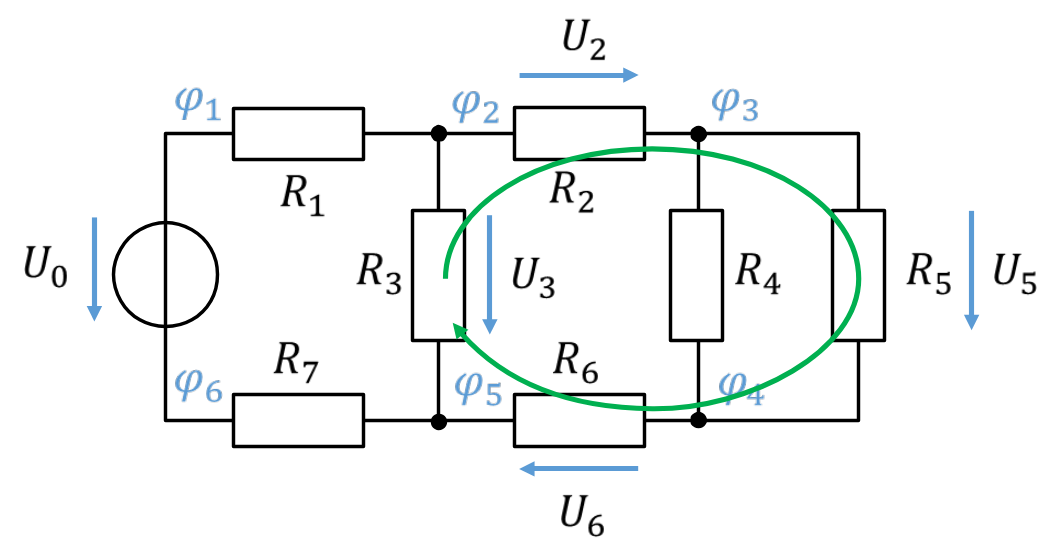
There are a total of 6 meshes in the circuit, from which partly redundant equations can be set up. So it is important to find the right mesh from whose equation the parameter you are looking for can be derived.