Summary: Filters
Low-pass filter
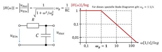
A passive low-pass filter made of a resistor and a capacitor has the following structure and transfer function:
An active low-pass filter has the following structure and transfer function:
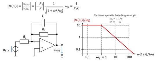
Note: the cut-off frequency and the gain do not depend on the circuit structure. You set these parameters with the components. That is why the gain and cut-off frequency in both circuits are only example values.
You use a low-pass filter when the interference frequency is higher than the useful frequency. The interference frequency then lies to the right of the useful frequency in the Bode plot.
You determine the attenuation from the distance between interference frequency and cut-off frequency. If, for example, the interference frequency is a factor of 100 higher than the cut-off frequency, the attenuation of the interference signal is D = 100. Note: it is about the distance to the cut-off frequency, not to the useful frequency!
For a low-pass filter, you place the cut-off frequency a factor of 10 higher than the useful frequency. Then the filter amplifies the useful signal by a factor of 1. The following applies:
High-pass filter
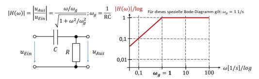
A passive high-pass filter made of a resistor and a capacitor has the following structure and transfer function:
An active high-pass filter has the following structure and transfer function:
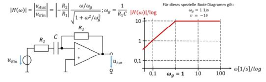
Note: the cut-off frequency and the gain do not depend on the circuit structure. You set these parameters with the components. That is why the gain and cut-off frequency in both circuits are only example values.
You use a high-pass filter when the interference frequency is lower than the useful frequency. The interference frequency then lies to the left of the useful frequency in the Bode plot.
You determine the attenuation from the distance between interference frequency and cut-off frequency. If, for example, the interference frequency is a factor of 100 lower than the cut-off frequency, the attenuation of the interference signal is D = 100. Note: it is about the distance to the cut-off frequency, not to the useful frequency!
For a high-pass filter, you place the cut-off frequency a factor of 10 lower than the useful frequency. Then the filter amplifies the useful signal by a factor of 1. The following applies:
Band-pass filter
A band-pass filter combines high-pass (HP) and low-pass (TP) behaviour in one circuit. An active band-pass filter has the following structure and transfer function:
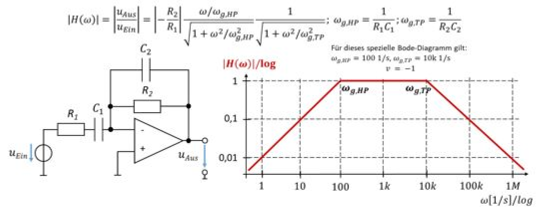
Note: the cut-off frequencies and the gain do not depend on the circuit structure. You set these parameters with the components. That is why the gain and cut-off frequencies in the circuit are only example values.
You use a band-pass filter when there are interference frequencies both lower and higher than the useful frequency. The interference frequencies then lie to the left and right of the useful frequency in the Bode plot.
You determine the attenuation from the distance between interference frequency and cut-off frequency, as explained for the high-pass and low-pass filters. You place the cut-off frequencies a factor of 10 on either side of the useful frequency. The following applies: