Power Electronics
Learning objectives
This tutorial is intended for students who will later assemble ready-made power electronics modules into installations. You will not develop new modules or optimise the modules. You will be able to select suitable modules for installations. You will connect and dimension modules, taking efficiency and costs into account. You will find faults in installations and, in the event of a failure, recognise where the fault lies.
The components of power electronics are covered only superficially. Their behaviour is explained, but not derived from physics. For example, it is not explained why an inductor has a field and which measures inside the inductor can reduce the field. We do discuss how fields act and, in particular, how magnetic coupling works, so that EMC measures can be taken in the installation.
You will know the basic circuits of power electronics and where in an installation you need which circuit.
At the end of the tutorial you will be able to calculate the power losses of power electronics components. You will consider not only individual components but their interaction as an overall system. You will be able to determine efficiencies. You will have a feel for costs. Using these parameters you can assess and optimise solutions. You will know basic circuits for power converters such as inverters and boost converters.
The tutorial focuses on a small to medium power class below 1 MW. You will later work in companies that develop or install energy-transition products for households, such as electric cars or PV systems.
Power electronics and the energy transition
Power electronics is a key technology for the energy transition. It deals with changing voltage and current with high efficiency. This is important for all forms of energy conversion and distribution. You will find power electronics in almost all areas of the energy transition, such as wind turbines, PV systems, electromobility, grids, etc.
The challenge
In this tutorial we consider circuits with an input voltage and an output voltage. The input voltage is often given, e.g. by the grid or by a high-voltage battery in an electric car. The output voltage differs depending on the application and the operating point. We need circuits whose output voltage differs from the input voltage. In general, the output voltages must be variable during operation.
In general, both the output and the input voltage can be DC or AC voltages. The DC voltage level or the peak value of the AC voltage can differ between input and output. The frequency of the AC signals is not always the same at input and output either. Altogether we consider 4 cases of power converters:
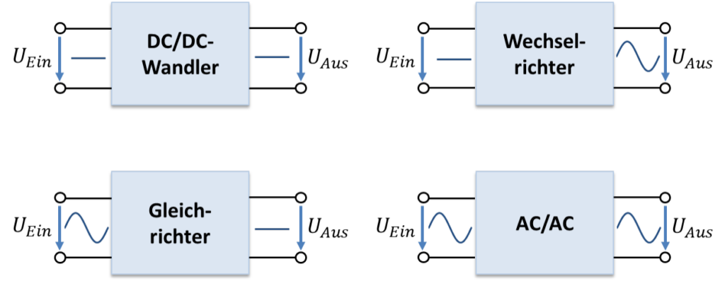
In power electronics, a decisive criterion for a good solution is efficiency. It indicates how much of the input power from the source is available at the load. In a good power converter, only about 1 % of the input power is lost as heat. We then speak of a power loss in the converter of 1 % or an efficiency of 99 %. It is calculated as follows:
(Index Ein: input, Aus: output, Leistungssteller: power converter.)
USB socket on the cigarette lighter
An everyday example of power electronics is providing a USB voltage at the cigarette lighter of a car. The voltage of the cigarette lighter is about 14 V, the USB voltage is 5 V. Both are DC voltages. Behind the cigarette lighter is the car battery as the source. You want to charge a smartphone from the USB voltage. So you connect a load (smartphone) that draws current (e.g. 1 A) from the USB voltage. We model the smartphone as an ohmic resistor.
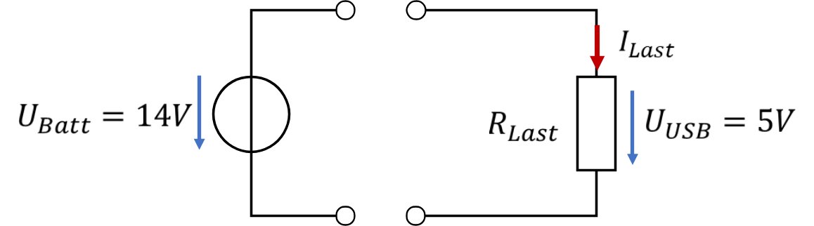
(Index Last: load.)
The source voltage is higher than the load voltage. We have to reduce the source voltage. In the fundamentals of electrical engineering we used a series resistor for this.
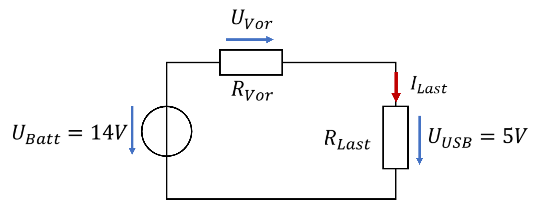
We have to set the series resistor so that the output voltage is right. For this, the difference between 14 V and 5 V must drop across the series resistor. The load current flows through the series resistor. We have:
(Index Vor: series resistor, Quelle: source.)
If we simply install a fixed 9 Ω series resistor, we have solved the problem only for the one load current of 1 A. Now someone with a different smartphone that draws 2 A of charging current uses our circuit. Now:
No voltage is left for charging; the series resistor is far too large. After all, it was dimensioned for the current I = 1 A. The “right” new series resistor is:
So we need an adjustable series resistor that changes its value depending on the load current.
Unsuitable approaches
Imagine we had a component whose resistance can be set by a control voltage. You can set the resistance freely between 100 mΩ and 1 MΩ. To do this, you only need to vary a control voltage between 0.5 V and 2 V.
A transistor behaves similarly to the description above. With this adjustable resistor we can solve the problem. If we install the transistor as a series resistor, we can create a suitable series resistance for each load current. To do so, we have to measure the load current (somehow) and adjust the control voltage. This kind of solution is called a linear regulator (series regulator); the transistor operates permanently in its linear region, as in a class A output stage.
Let us look at the power losses and the efficiency of this solution when charging with a load current of 1 A:
Only 35.7 % of the power taken from the car battery reaches the smartphone. A solution with such a low efficiency is completely unacceptable when a lot of power is involved. We can still get away with it in an insignificant USB charging circuit, but not in the energy transition. Imagine a local substation that transforms 10 kV down to 400 V or 230 V had an efficiency of only 35.7 %. Such a substation supplies a small housing estate with energy. More than half of the power station would then work only to cover the losses in the substation, and less than half of the energy would reach the households.
A suitable approach
There must be better solutions. There are, and they are what this tutorial is about. The better circuit looks like this:
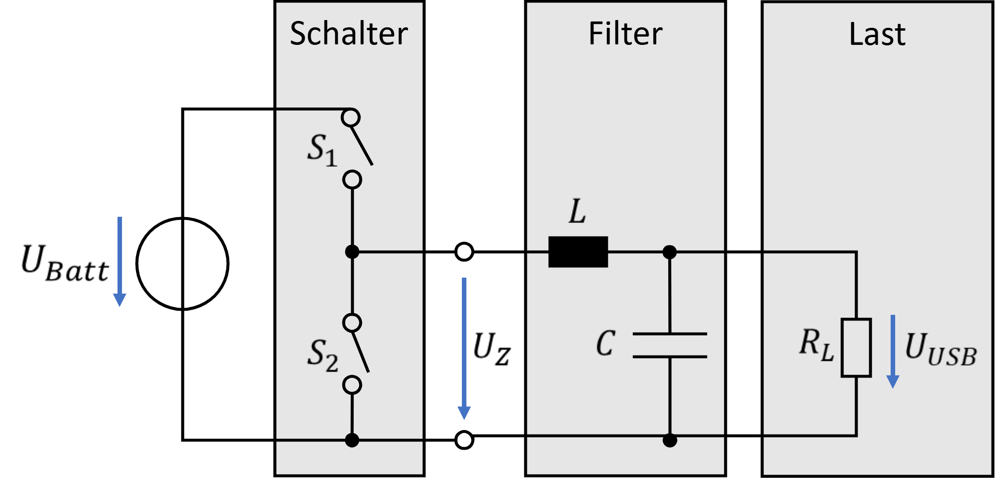
The battery voltage is first converted into an intermediate voltage by two switches. From the DC voltage we first generate a “chopped” voltage. The average value of the chopped voltage is 5 V. Its time response is shown in the upper curve of the following figure. The voltage consists of portions of 14 V and 0 V. If switch S1 is closed and S2 is open, UZ is 14 V. If switch S2 is closed and S1 is open, UZ = 0 V.
For 35.7 % of the time the voltage is 14 V and for 64.3 % of the time it is 0 V. On average over time, this results in the USB voltage of 5 V. In the next chapters we will look closely at switches to understand this stage better.
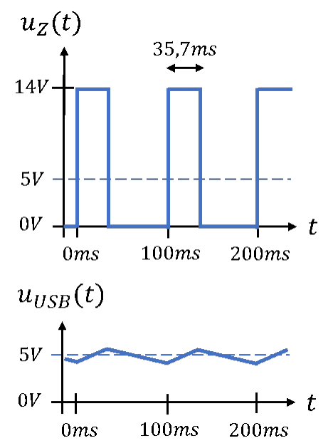
The voltage is then filtered with an inductor and a capacitor. To understand the filtering effect, we first need to look more deeply at the inductor and the capacitor. At the output there is a smoothed voltage that fluctuates slightly around 5 V. It is not yet clear where these voltage curves come from. You will understand them by the end of the tutorial.
Let us look at the power loss again. An ideal switch has no power loss. Either the voltage across the switch is 0 V (closed state) or the current is 0 A (open state). Voltage and current are never present at the same time. P = U ∙ I = 0 W always holds.
Ideal inductors and capacitors have no power loss either. They only have reactive power and no active power, see Fundamentals of Electrical Engineering / Alternating Current. If no active power is dissipated in the components, theoretically the entire input power is available at the output with an efficiency of 100 %. Of course this is not the case in practice; we will look at this in more detail later. In practice, such a circuit has an efficiency of about 98 % to 99 %. That is something we can work with in the energy transition.
Power electronics deals mainly with high-power systems in which the load voltage does not equal the source voltage. Classic criteria for assessing these solutions are:
- Efficiency
- Costs
- System costs (e.g. cooling)
- Installation space
- Power factor / reactive power
We will assess and optimise solutions according to these criteria.