Inductor
An inductor (coil) is an electrical energy store. The internal function of an inductor can only be understood with extensive prior knowledge of magnetic fields. The inductor is not very intuitive, and I cannot think of a good analogy for how it works. We therefore treat the inductor as a black box and limit ourselves to its use in circuits.
An inductor has two electrical terminals. The symbol of the inductor is a filled rectangle with two terminals. You can fill a resistor symbol black and you get the symbol of an inductor. In American publications – and unfortunately also in the simulation program – a wound wire is used as the symbol.
The ability to store energy is described by the property inductance of the inductor. The inductance has the symbol L and is given in the unit henry (H). It characterises the inductor.
| Physical quantity | Symbol | Unit name | Unit symbol | Circuit symbols |
|---|---|---|---|---|
| Inductance | \(L\) | Henry | \(1\,\mathrm{H} = 1\,\Omega\mathrm{s}\) | 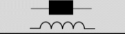 |
In the simplest case, the inductor consists of an insulated wire wound around a special core. If a current I flows through the wire, a voltage U drops across the inductor. Like capacitance and resistance, the inductance L depends on geometry and material parameters. The following applies:
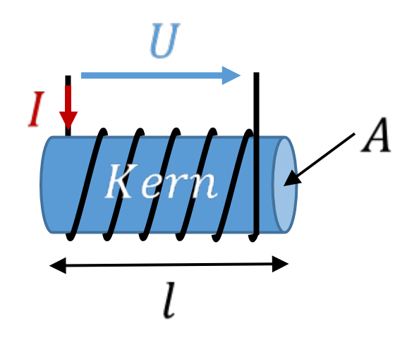
Just as with the capacitor, the formula contains a material parameter and a natural constant. The value of µr is chosen so that it takes the value 1 for air. An inductor in which the wire is simply wound in a cylindrical shape in air without a core therefore has the material parameter µr = 1.
The inductance depends on the geometry parameters core length and core cross-sectional area. The number of turns is particularly important, because it enters the inductance value squared.
Optimising the inductance
A good inductor for use in a smartphone, for example, has a large inductance with a small physical size. So we cannot make the area A arbitrarily large. Nor can we make the length l of the core arbitrarily small, because the turns of the wire are wound onto the core. The wire needs space. We can use wire that is as thin as possible and wind it on top of and next to each other. This makes l smaller.
The parameters N and µr have the greatest influence on the inductance. N acts squared and thus much more strongly on the inductance than the geometry parameters, which is why N is often chosen to be large. The parameter µr differs depending on the material. It can take values of µr > 100000. So with the right core material, even a geometrically small inductor achieves very high inductance values.
Relationship between voltage and current
For the inductor, the following applies:
All quantities of the inductor behave reciprocally to the quantities of the capacitor. In the formulas for the capacitor, you swap L for C and U for I. This gives you the formulas for the inductor. What applies to the voltage at the capacitor applies to the current at the inductor.
Energy
With regard to energy, too, the behaviour of the inductor is reciprocal to that of the capacitor:
So the energy stored in an inductor is proportional to the inductance L and to the square of the current I.
Optional: use in a circuit
This section is not relevant for the exam. It serves as an explanation, but is more difficult to understand than the previous sections.
A capacitor always has a continuous voltage curve. The voltage cannot “jump” over time. The capacitor smooths a voltage; it keeps it constant even if the load draws current from it in pulses. You can also see this in the bucket model: the fill level of the bucket does not jump, it changes continuously with the inflow.
Reciprocally, the inductor always has a continuous current curve. An inductor is therefore used where a current that is as constant as possible is needed, where a current is to be smoothed. A good example is generating a current that is as constant as possible using pulse-width modulation. To do this, we take a short detour into digital technology.
So far, you have got to know voltage sources that can output any voltage value. Within circuits, there are also voltage values of different heights across different resistors. In digital technology, this is different. Digital technology uses the base-two or binary system. Here, two states “high” and “low” are distinguished, expressed as numbers “1” and “0”. This is explained well in this Wikipedia article. In a system operated from a 3 V battery, for example, the voltages ULOW = 0 V and UHIGH = 3 V are assigned to the two states.
At an output terminal (pin) of a microcontroller, which is controlled by a software program, i.e. from the digital world, only the voltages 0 V and 3 V can be present. Intermediate values are not possible. You will learn more about this in later lectures.
In power electronics, the electric motor of an electric car is operated either with the output voltage of the car's battery (currently generally approx. 400 V) or with the negative battery voltage (i.e. −400 V). Intermediate values between these voltages cannot be output by the inverter. This is covered in more depth in later lectures. The electric motor needs a current that is as constant as possible, even though the voltage can only be switched between two values.
This can be modelled as a voltage source with an output voltage that varies over time. Since the voltage has the shape of a rectangle over time, the symbol of the voltage source is modified.
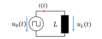
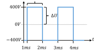
Because the source and the inductor are connected in parallel, UL = U0. The voltage across a motor in an electric car over time can, in simplified form, look like the lower part of the figure above.
We will not go into how an inverter or a microcontroller generates this voltage curve. The current of the inductor equals the integral of the voltage over time – i.e. the sum of the voltage over time. For an example inductor with L = 10 mH, the following applies:
So the current rises by a total of 40 A as long as the positive voltage is applied. At the time t = 2 ms, it is 140 A. To calculate the current at the time t = 3 ms, we use the current at t = 2 ms as the value IL0 = 140 A and again calculate the voltage-time area between t = 2 ms and t = 3 ms:
During this time, the current falls by 40 A from 140 A back to 100 A. The current over time looks like this:
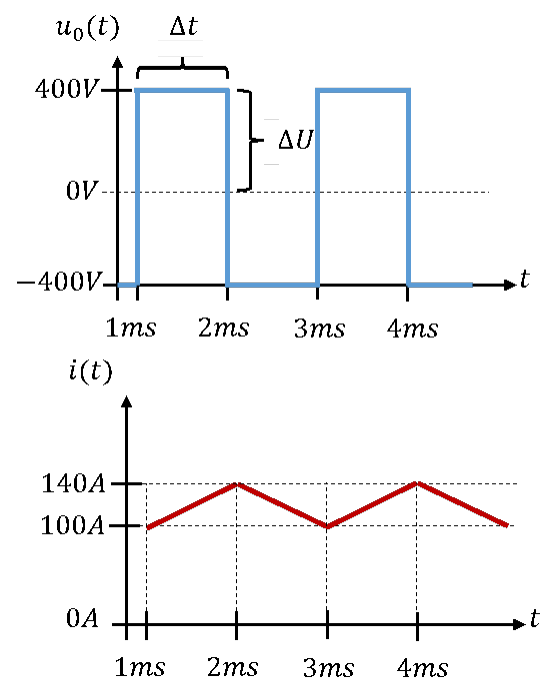
The time average of the current is 120 A. It has a triangular shape with a DC component equal to the mean value of 120 A and an AC component of ±20 A. The larger the inductance of the inductor, the smaller the AC component of the current. So a good inductor with a high inductance smooths current better than a poor one with a low inductance.
Further information: Inductor in power electronics
Split by degree programme
At this point, the electrical engineering tutorial splits depending on the degree programme.