Real Current Source
A real current source has an output current that depends on the output voltage. This is modelled by a high-resistance resistor placed in parallel with an ideal internal current source. Part of the source current flows into this resistor, namely the error current IF.
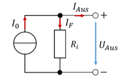
Only a reduced output current is available at the terminals of the real current source. The higher the output voltage, the higher the voltage across the internal resistance. As a result, the error current increases and the output current decreases.
We again determine the parameters of the equivalent circuit in open circuit and short circuit. Short-circuiting a current source is not a problem. It then simply pushes the output current through an ideal short-circuit conductor. In the short circuit, the following applies:
At this operating point, we measure the short-circuit current. The short-circuit current equals the current of the internal ideal current source. In open circuit, no load is connected to the output terminals. The following applies:
In open circuit, we measure the output voltage. From the open-circuit voltage and the short-circuit current, we again determine the internal resistance of the real current source.
Let us look at a numerical example:
The deviation in this example is 1 % of the nominal current.
The idea of a power source
It is not possible to specify both the voltage and the current of a source at the same time. One of the two parameters can be fixed; then the other must be flexible. Otherwise it would be mathematically impossible to operate different resistors on the source.
Problem: Check whether a source can specify voltage and current at the same time. To do this, model an ideal combined voltage/current source that specifies both the output voltage U = 5 V and the output current I = 1 A and is operated with a resistor R = 1 Ω as the load. Do you see why this cannot work?