Decoupling Circuit Sections
For the measurement chain, we connect function blocks together as circuit sections. We determine the transfer functions of the individual blocks and then multiply them. For this approach it is important that connecting the circuit sections does not impair their function. In this chapter I explain how such an impairment can come about.
Water model
If you only want to prepare quickly for the lecture, you can skip the part on the water model up to the next heading.
For the explanation, let us look at the water model. You build a circuit that drives a small water wheel. For this you have a water source available in the form of a lake. You can choose a pipe through which exactly the right amount of water flows from the source onto the little wheel. The wheel turns exactly as fast as it should. If the pipe were thicker, too much water would flow. If it were thinner, too little water would reach the wheel. The circuit works wonderfully and you are happy.
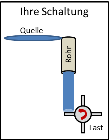
Someone has the idea of using your circuit in a measurement chain. So it is installed between two other circuits. The output of your circuit is the input quantity of the next circuit. In electrical engineering this means: the output voltage of your circuit is used as the input voltage of the next circuit.
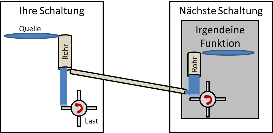
There is a connection between the circuits. The other circuit draws some water from the bottom of your pipe – without asking. This happens automatically as a result of connecting them. Now your wheel turns too slowly, because water is missing. You notice this and fiddle with the internal pipe until the amount of water is right again.
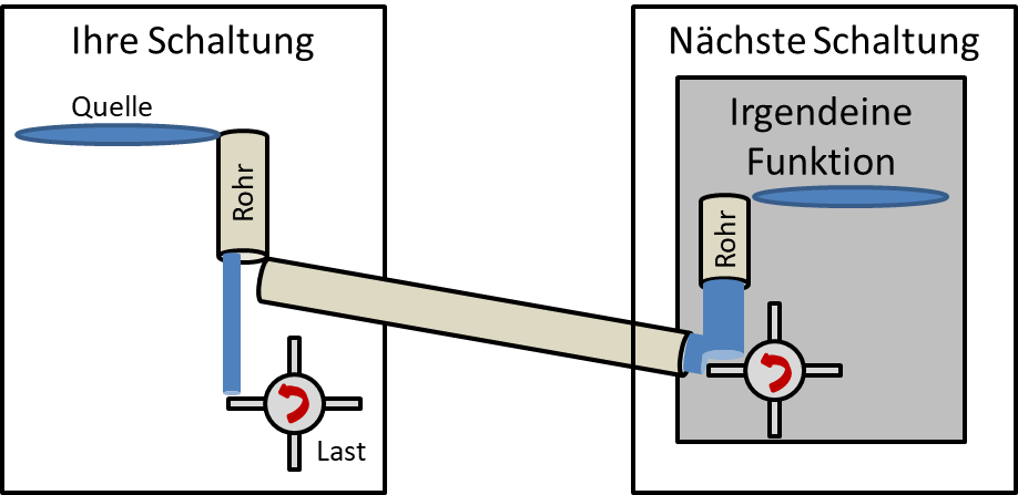
Now the next person comes along and connects a slightly different circuit to your circuit, one with a slightly thicker pipe. It draws more water out of your circuit. This way you cannot build a circuit that anyone can simply integrate directly into a measurement chain. You cannot adapt the pipe every time, especially if you sell 100,000 identical circuits. What can you do?
1. You can make sure that, ideally, no water at all flows out of your circuit. If you are a nice engineer, you also make sure that no water flows from the previous circuit into your circuit. How can this be achieved? The pipe at the input of each circuit, with which it taps the circuit in front of it, must be as narrow as possible.
2. You can make sure that there is always enough water available at the output of your circuit. Then it does not matter how much the circuit after you draws off. Ideally, you have a lake with an infinite amount of water at the output of your circuit, whose water level is always constant.
The problem in electrical engineering
Back to electrical engineering. When you connect two circuits, current generally flows from one circuit into the other. This affects the function of the circuits, because you do not know in advance how much current the other circuit draws.
As an example, let us take a PT100 as a sensor on a current source with I0 = 10 mA. We connect the sensor to an inverting amplifier. We now replace the ideal voltage source in front of R1 with a sensor. The following circuit diagram results:
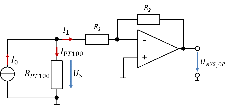
Let us look only at the sensor on the far left. So far we have assumed that the current of the current source flows completely through the PT100. Then the sensor voltage is US = RPT100 ∙ I0.
Because of the connection to the amplifier, however, part of the source current flows through R1 and R2. I call this current I1 in the figure. With the node equation, the current through the PT100 is then:
The current I1 is not determined by the sensor section of RPT100 and current source, but by the next circuit connected to it.
For the current I1 (left mesh of the inverting amplifier):
The current that causes the error also depends on the sensor voltage, i.e. on the measured quantity temperature. The effect can be corrected digitally, but it is more elegant to avoid it.
If an op-amp circuit is used into which no current flows, the effect does not occur in the first place. For example, we can install a buffer between the sensor and the inverting amplifier. The circuit then looks like this:
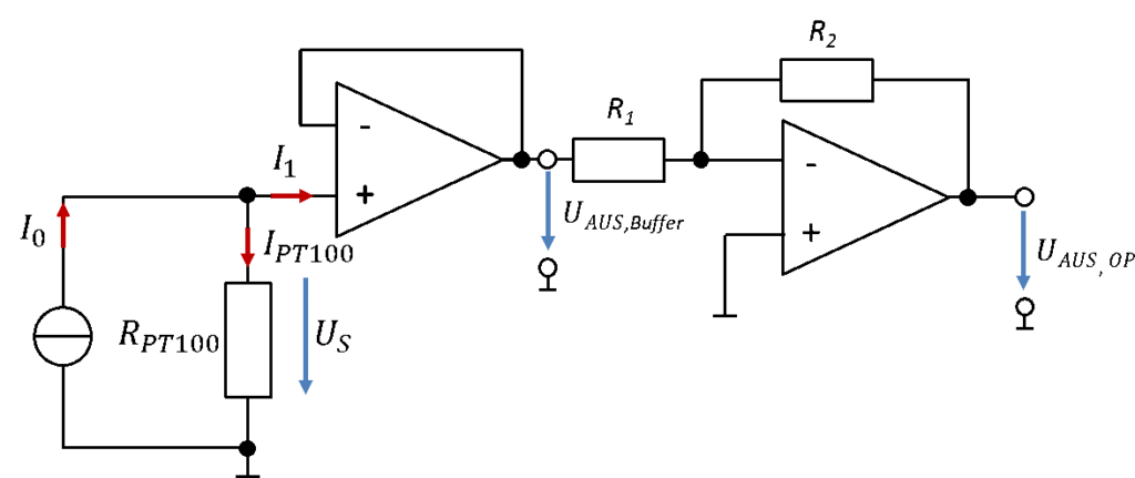
Since the buffer has the transfer function H = 1, the overall transfer function does not change, because it is only multiplied by a factor of 1. The source current now flows completely through the PT100, because no current flows into the input of the buffer. The current at the output of the buffer is not critical, because the output of an op-amp forms an ideal voltage source. So the output voltage of the buffer is independent of the output current. However, we now need an additional op-amp in the circuit. And that costs money.
Alternatively, we can also use a non-inverting amplifier:
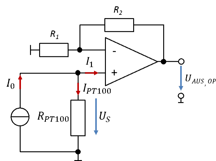
Here, too, no current flows into the non-inverting input of the op-amp. The gain is now positive. You can see that there are different solutions. What all solutions have in common is that we use op-amp circuits to ensure that no current flows from the sensor into the analogue signal processing. If no current flows between the blocks (or only so little that the effect on the measurement uncertainty is sufficiently small), we call the two circuit sections “decoupled”.
Decoupling with differential signals
We connect a bridge circuit and a differential amplifier. For this we have to check whether current flows from the bridge circuit into the differential amplifier and whether this is a problem. Currents of different magnitude flow into the two inputs of the differential amplifier.
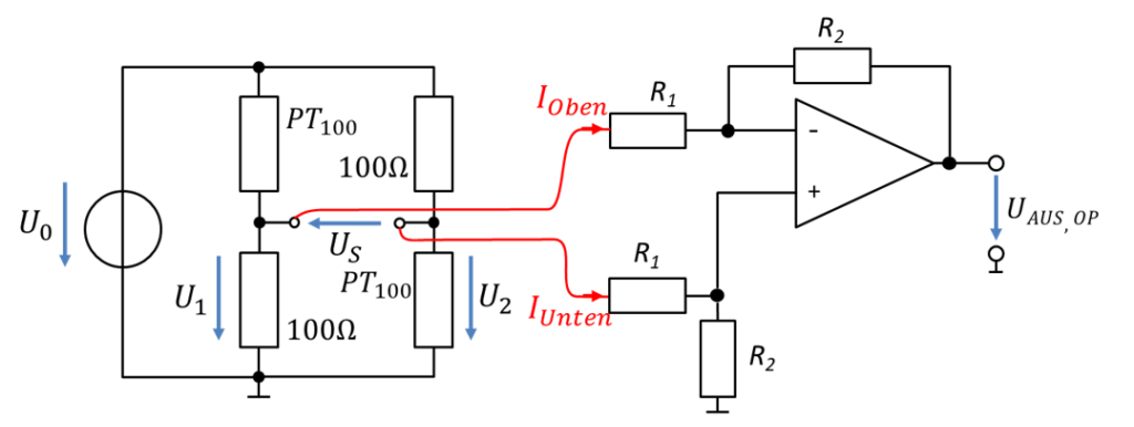
(Oben = upper, Unten = lower.) To calculate the sensor voltage at the bridge, we assumed that no current flows out of the bridge circuit. It becomes clear that the sensor voltage changes when the circuit sections are connected, even though the temperature does not change. So we make an error. This error also depends on the temperature, because it depends on φ1 and φ2. It is difficult to calculate and therefore can only be corrected digitally with considerable effort.
The simpler solution is the instrumentation amplifier. Here, both outputs of the bridge circuit go directly to op-amp inputs. Therefore no current flows out of the bridge circuit. The bridge is decoupled from the amplifier. This solution looks as follows:
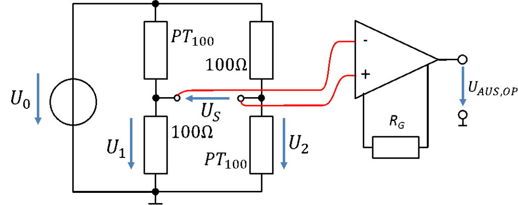
An instrumentation amplifier is always needed when the current into the inputs of the amplifier circuit becomes so high that the measurement uncertainty becomes unacceptably large.