Series Connection
Two components are connected in series if there is no node between them at which the current splits. You can use this feature to check whether there is a series connection in a circuit. Let us look at the following example:
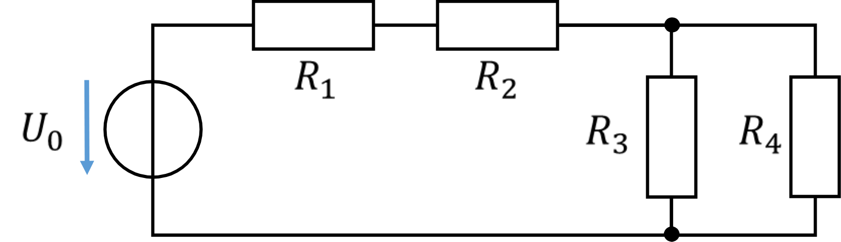
In the example circuit, the resistors R1 and R2 are connected in series. Since there is a node between R2 and R3, no further resistors are connected in series. The simplest case is the series connection of two resistors:
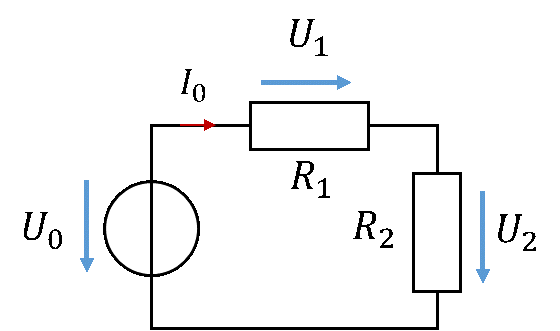
In a series connection, the same current flows through both components, because there is no other path for it. Let us apply the node rule and the mesh rule to this:
In a series connection, the voltage U0 splits into the two partial voltages U1 and U2 according to the mesh rule. In general, more than two components can be connected in series.
In complex networks, components are connected in series at many points. Calculating the distribution of voltage and current in the network is easier if all components connected in series are combined into a single equivalent resistor RGes. This reduces the computational effort when the distribution of voltage and current in a complex circuit is to be determined. The equivalent resistor is dimensioned so that the original circuit and the circuit with the equivalent resistor behave in the same way.
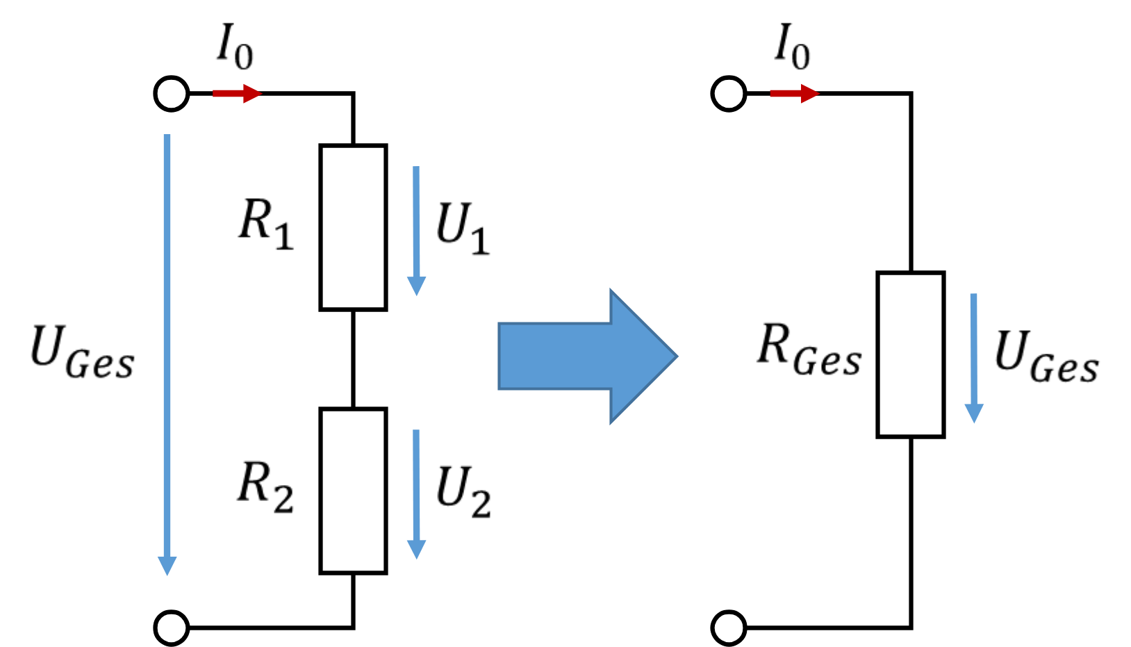
The two circuits on the left and right behave identically from the outside if the voltage and current at the equivalent resistor are exactly the same as at the series connection of R1 and R2. Then the following applies:
Numerical example: in a series connection of two resistors, the following applies:
For the same current, the same voltage drops across both circuits. So the circuits behave in the same way. Further calculations in the circuit are much easier with one equivalent resistor than with several resistors. You only combine resistors so that you can calculate more easily. You do not have to do this; it just helps.
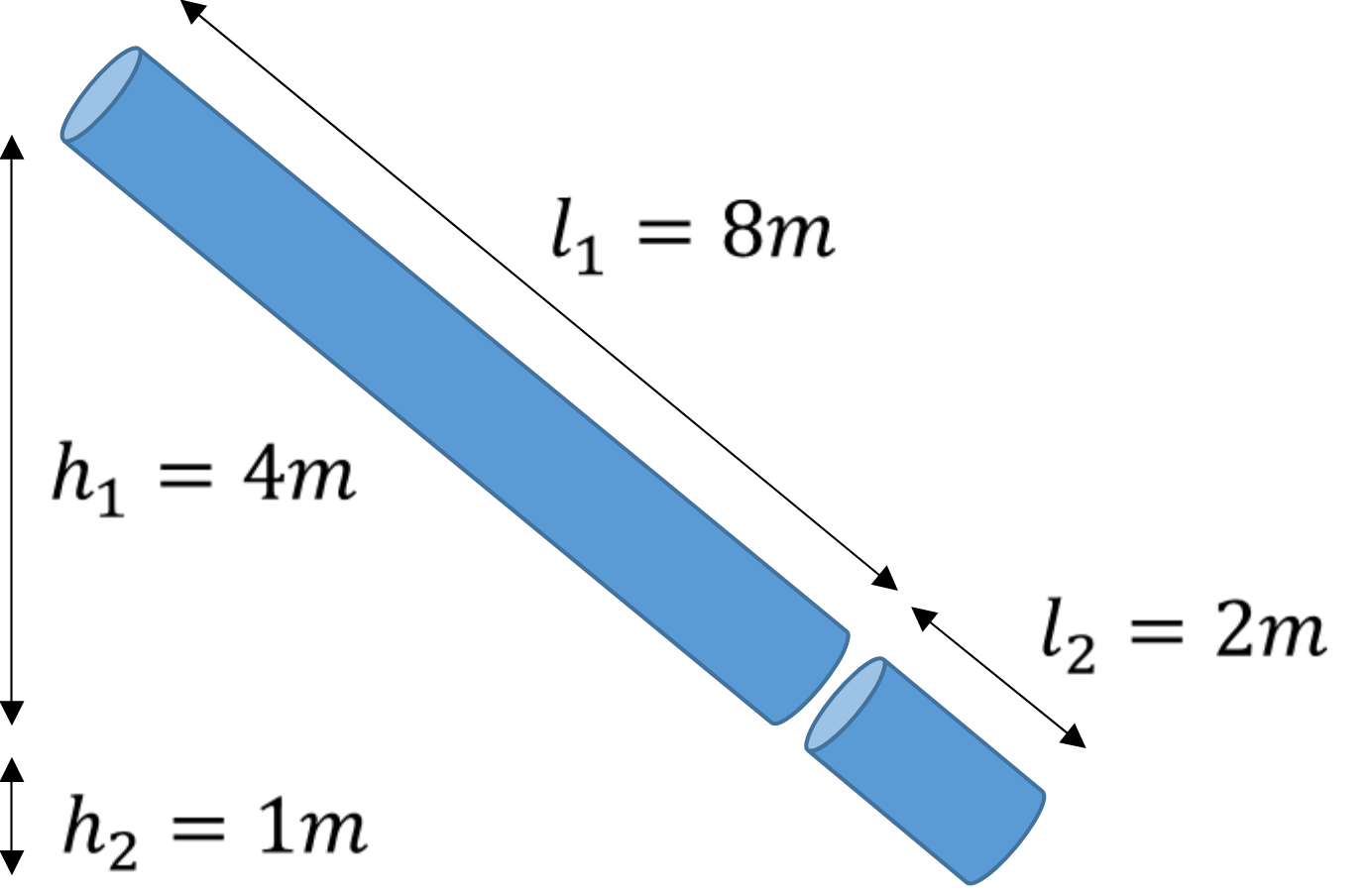
In the water model, a series connection can be understood as two pipes connected one after the other. For simplicity, let us assume that the pipe diameter and the material coefficient of both pipes are the same.
The first pipe, which represents R1 = 8 Ω, is l1 = 8 m long. It has a difference in height of 4 m over its length. The second pipe, which represents R2 = 2 Ω, is l2 = 2 m long. It has a difference in height of 1 m over its length. Together, the pipes have a length of lGes = 10 m and a difference in height of 5 m. Evidently the two pipes, when connected one after the other, have the same properties as one pipe that is 10 metres long, provided the total difference in height is the same. The same amount of water (current) will flow through both types of pipe (same resistance) for the same difference in height (voltage). It is easier to calculate with one pipe than with two.
What is this good for, and where is the advantage in practice? Let us look at the following example network:
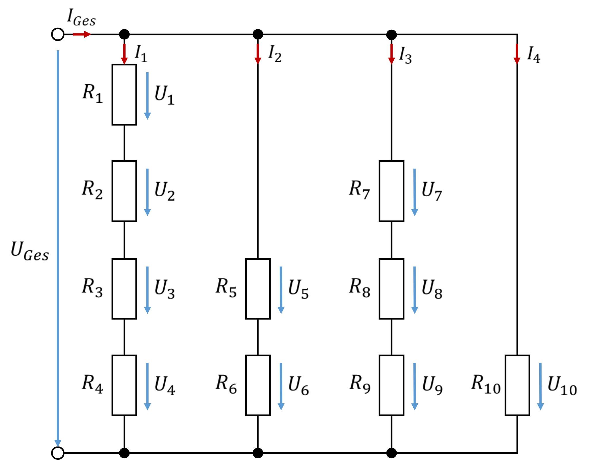
Determining all voltages and currents in the network is mathematically challenging. In cases where we are only interested in the total current flowing into this network and the total voltage across the network, combining all resistors in series helps. First we check which resistors are in series. Since, for example, there is no node between R1 and R2, these resistors are connected in series. The same applies to all 4 resistors R1 to R4.
Since the same current flows through all these resistors, because there is no node between them where current could flow away, they are connected in series. Combining all resistors connected in series in each of the 4 branches of the circuit leads to the following simplified equivalent network:
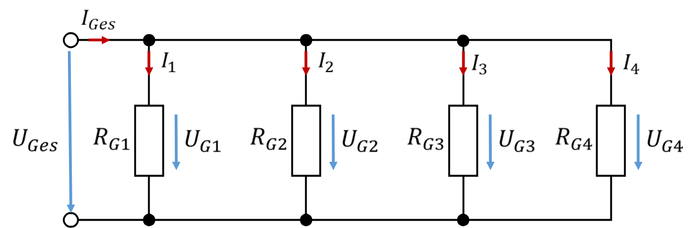
Voltages and currents in this equivalent network are easier to calculate, because the complexity of the circuit has been significantly reduced.
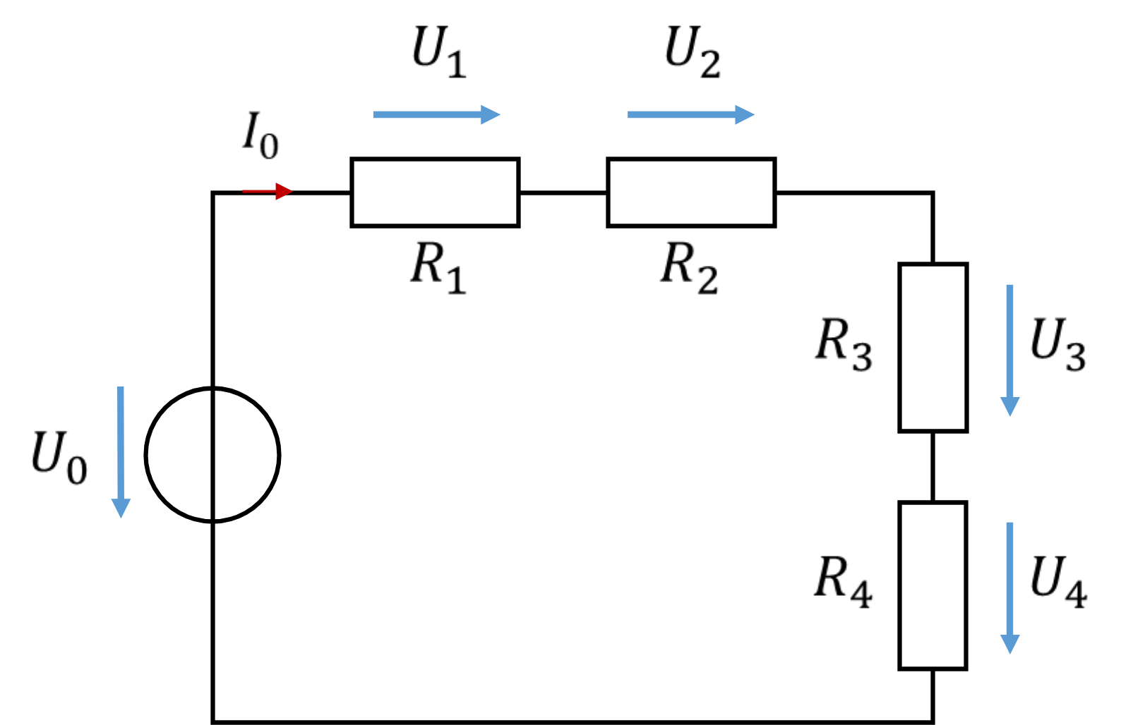
Problem: Determine in general the current and voltage equations of the following circuit:
Solution: