Current Measurement
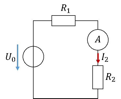
The current through the resistor R2 is to be measured. The current flowing through the resistor should also flow completely through the current measuring instrument called an "ammeter". That is why we connect the ammeter in series with the resistor, i.e. one after the other. The current cannot leave the cable, and the current before and after a component is always the same. This ensures with a series connection that the entire current through R2 also flows through the ammeter. For an ammeter, we use the symbol of a circle with an A inside.
The following circuit diagram shows, as an example, the measurement of the current I2 in the circuit with an ammeter:
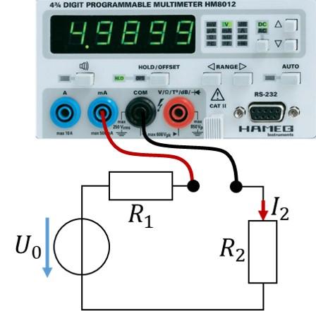
If the multimeter is to work as an ammeter, it must be switched to current measurement using the mode buttons. The current must flow into the blue socket and out of the black one. To measure small currents in the lab course, the right-hand blue socket (mA) is always used. The following figure shows how current measurement with an ammeter is realised in the lab:
The current measurement should not disturb the function of the circuit either. Therefore no voltage may drop across the ammeter. The resistance of an ammeter is therefore extremely small, close to 0 Ω. The voltage across this resistance is always 0 V:
This automatically ensures that voltage and current are not influenced by the ammeter.
You can connect the ammeter before or after the component whose current you want to measure. Because the current before and after a component is the same, this makes no difference.