A/D Converters
Analogue-to-digital converters are abbreviated “ADC”. They convert an analogue input voltage into a number. With the (digital) number, we can carry out further calculations in a microcontroller. A number can be output to a person or a machine as the result of a measurement. The ADC comes after the analogue signal processing. The block diagram looks like this:
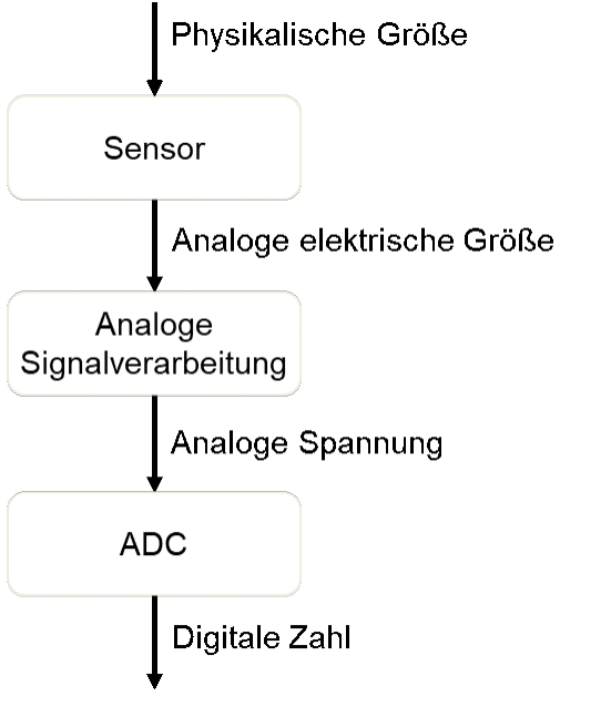
The ADC is explained before the analogue signal processing because it determines the requirements for signal conditioning in the analogue signal processing. It takes a voltage from the previous function block and digitises it – i.e. it converts it into a number.