Operation in a Voltage Divider
If a PT100 measuring resistor is operated in a voltage divider with a fixed resistor of R = 100 Ω on a fixed voltage source U0 = 3 V, we have the following circuit:

\[
\text{Voltage divider: } U_S = U_0 \cdot \frac{R_{\mathrm{PT100}}}{100\,\Omega + R_{\mathrm{PT100}}} = U_0 \cdot \frac{100\,\Omega + 0.4\,\frac{\Omega}{°\mathrm{C}} \cdot T}{100\,\Omega + 100\,\Omega + 0.4\,\frac{\Omega}{°\mathrm{C}} \cdot T}
\]
This is a non-linear equation; with the values given above, the voltage plotted against temperature looks like this:
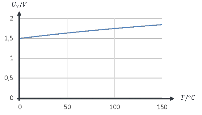
This does not correspond to our ideal of proportional behaviour. Starting from an initial value of 1.5 V, the sensor voltage rises slowly and non-linearly with temperature. There are better solutions.